Background
Sometimes I do stupid stuff like editing my firewall rules at home from a remote location and get myself locked out. Sometimes my internet connection is just broken for one reason or the other, this is when you need a out of band channel to your network. You can buy pretty expensive integrated hardware for this with 3G connection and serial consoles and so on, but since this is a project for my home network i decided to build something using a raspberry pi.
Prerequisites
To get this project going I wanted to have a raspberry pi, some sort of wireless connectivity and a serial console to my router.
So I got a Raspberry Pi 2B, this pretty neat case, a old Huawei E1752 from ebay and finally a Linocell Powerbank as a battery backup. For the actual mobile data I got a pre paid SIM card from Telia and got a few GB of data.
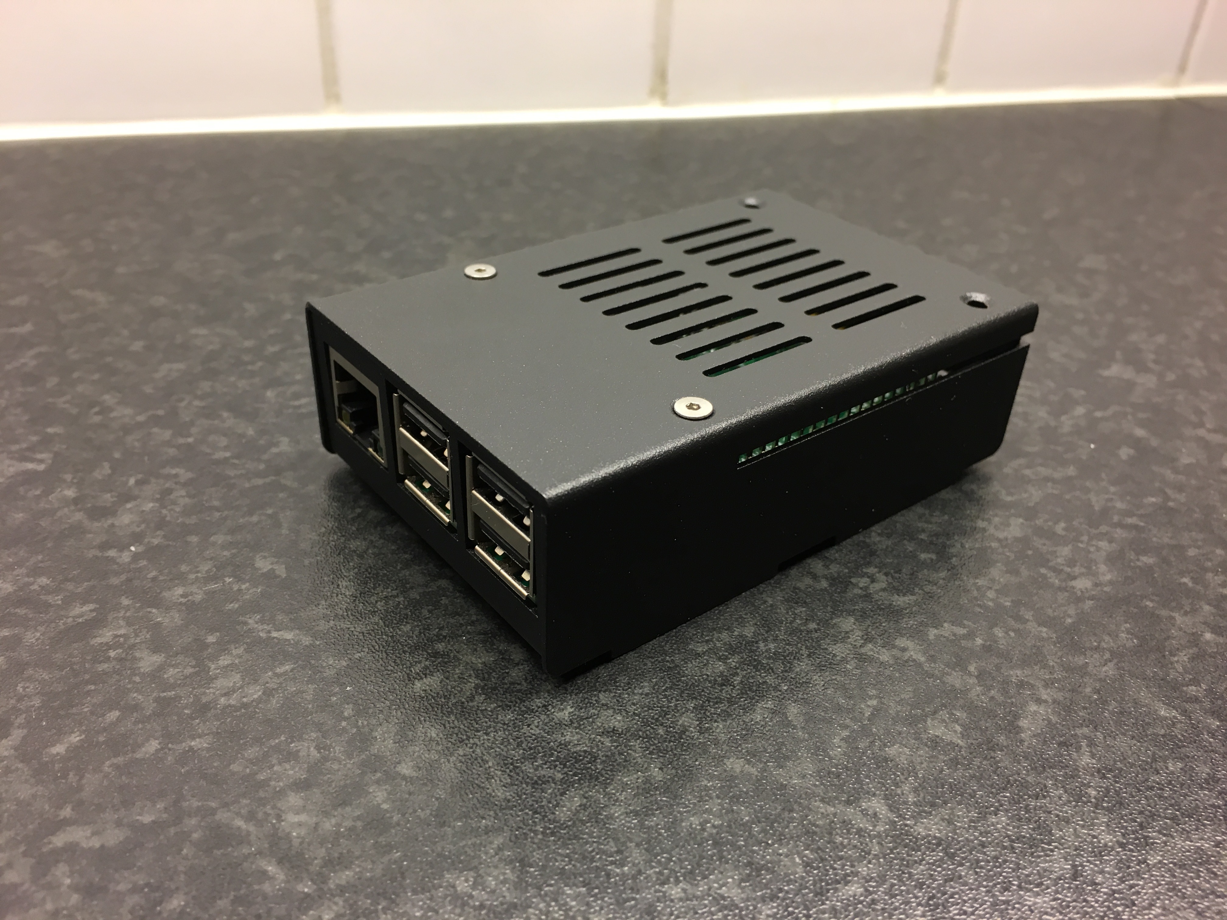
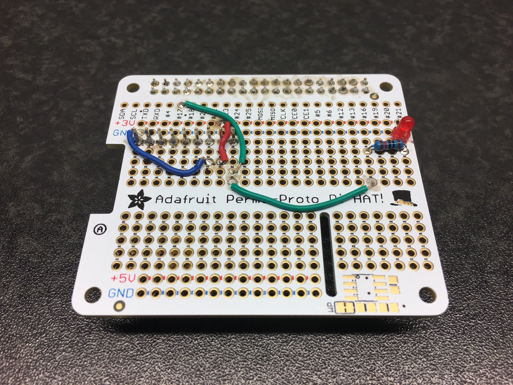
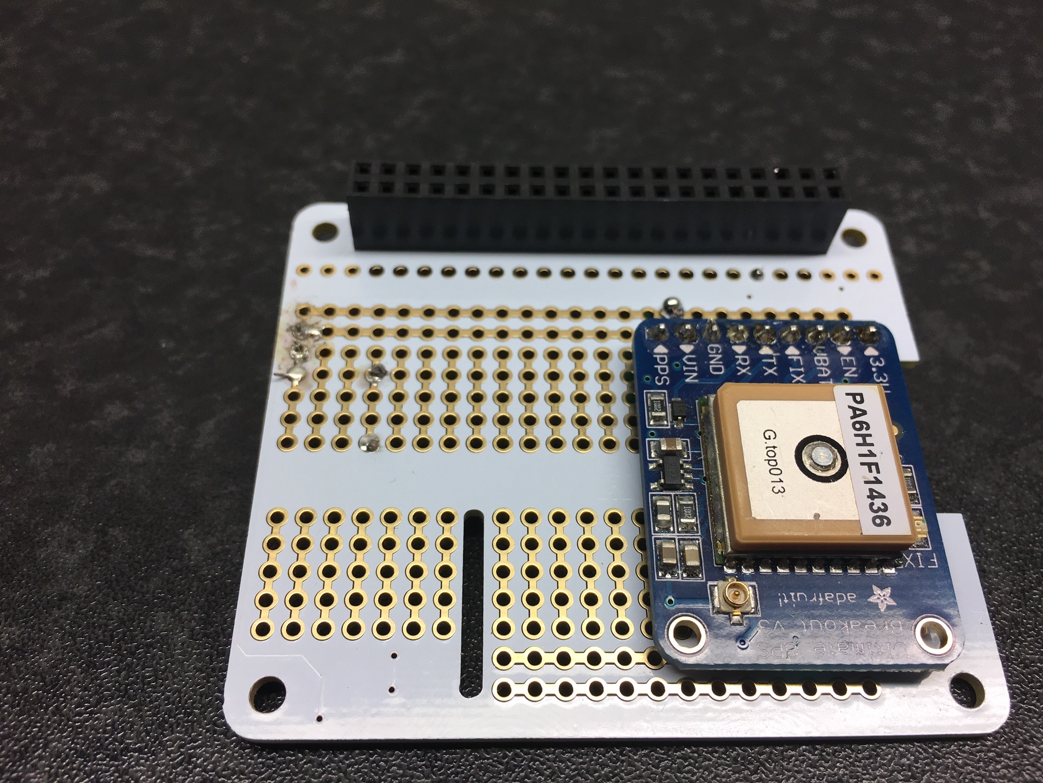
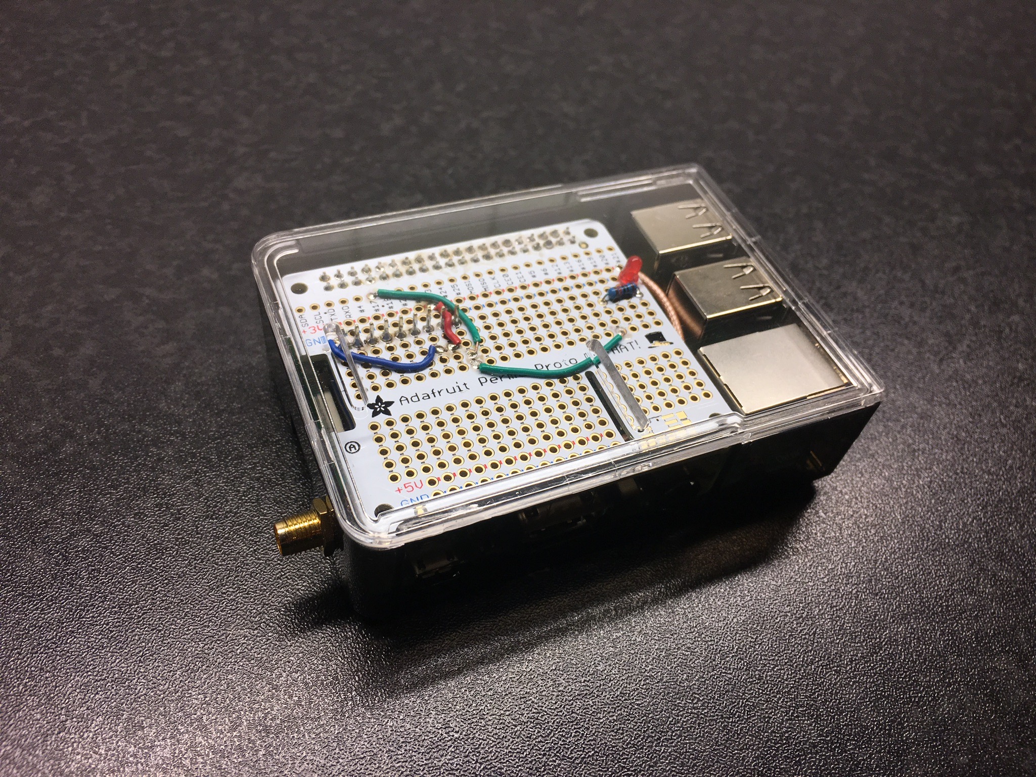
Raspberry Pi in case
Physical setup and operating system
This setup is very basic and I just put the Pi inside the case and installed FreeBSD using the official image from freebsd.org. I draw power from the powerbank to the pi, and the powerbank is permanently hooked up to power, this way it will run for maybe an hour or so in the event of a power failure.
3G configuration
The reason i got the pretty old E1752 was because it was dirt cheap and also I was absolutley positive it was supported by the u3g driver in FreeBSD.
It is very easy to set up actually, you just put in into a USB port of your Pi and it shows up as three serial interfaces (and maybe some storage device). The first thing you should do is to put the modem in “modem only” mode by sending some AT-codes
# cu -l /dev/cuaU1.0
AT^U2DIAG=0
OK
Then its time to get nostalgic! edit the /etc/ppp/ppp.conf. This was the first time for me since 1998 or something. Of course you will need to figure out some stuff about your 3G provider and make changes accordingly
default:
 set log Phase Chat LCP IPCP CCP tun command
 set device /dev/cuaU1.0
 set timeout 180

telia:
 set speed 115200
 set timeout 0
# set authname wapuser1
# set authkey wap
 set dial "ABORT BUSY TIMEOUT 3 \
        \"\" \
        AT OK-AT-OK \
        AT+CFUN=1 OK-AT-OK \
        AT+CMEE=2 OK-AT-OK \
        AT+CSQ OK \
        AT+CGDCONT=1,\\\"IP\\\",\\\"online.telia.se\\\" OK \
        ATD*99# CONNECT"
 enable dns
 resolv writable
 set ifaddr 10.0.0.1/0 10.0.0.2/0 255.255.255.255 0.0.0.0
 delete! default
 add! default HISADDR
then just test the connection by running “service ppp onestart”
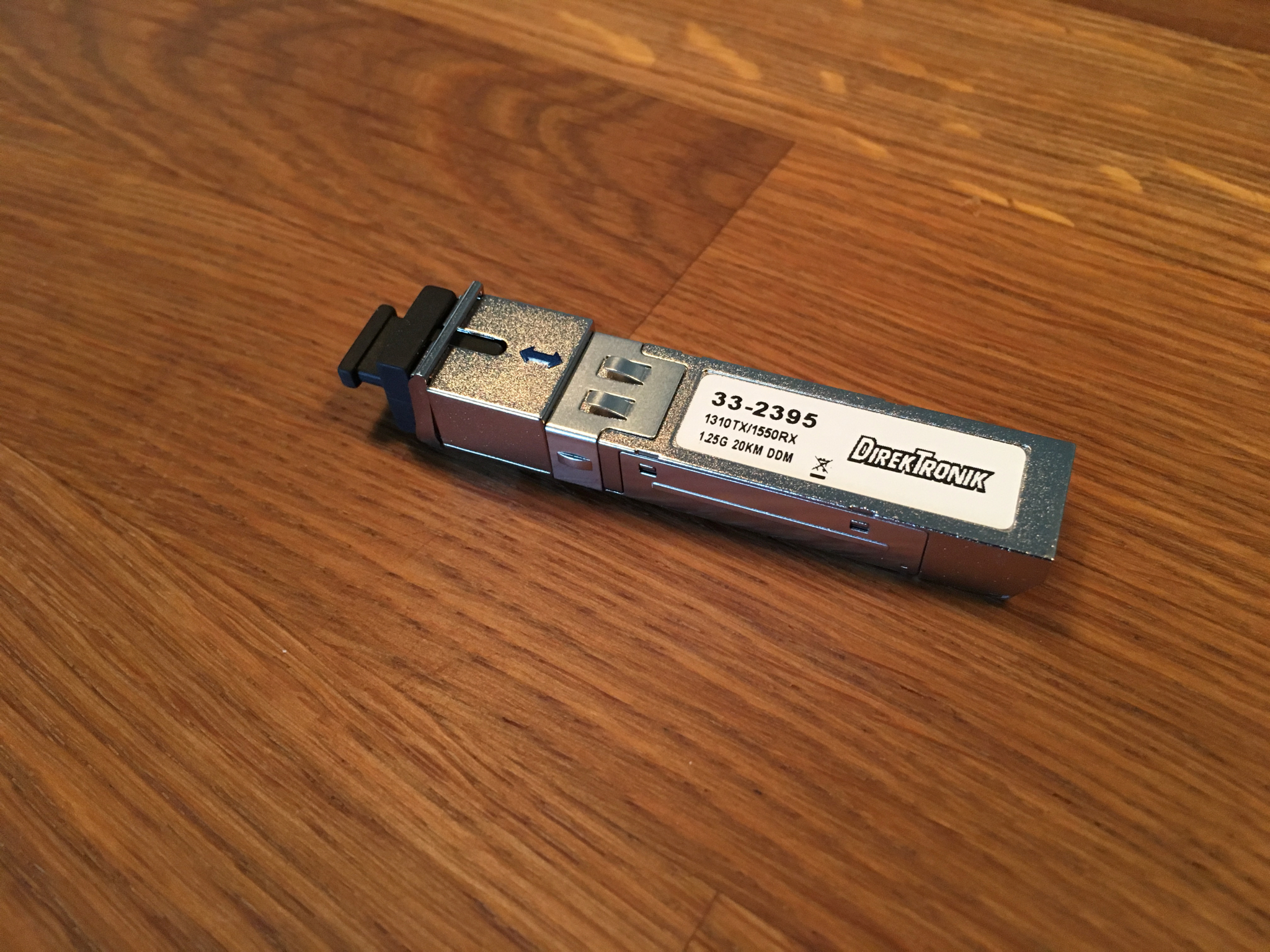
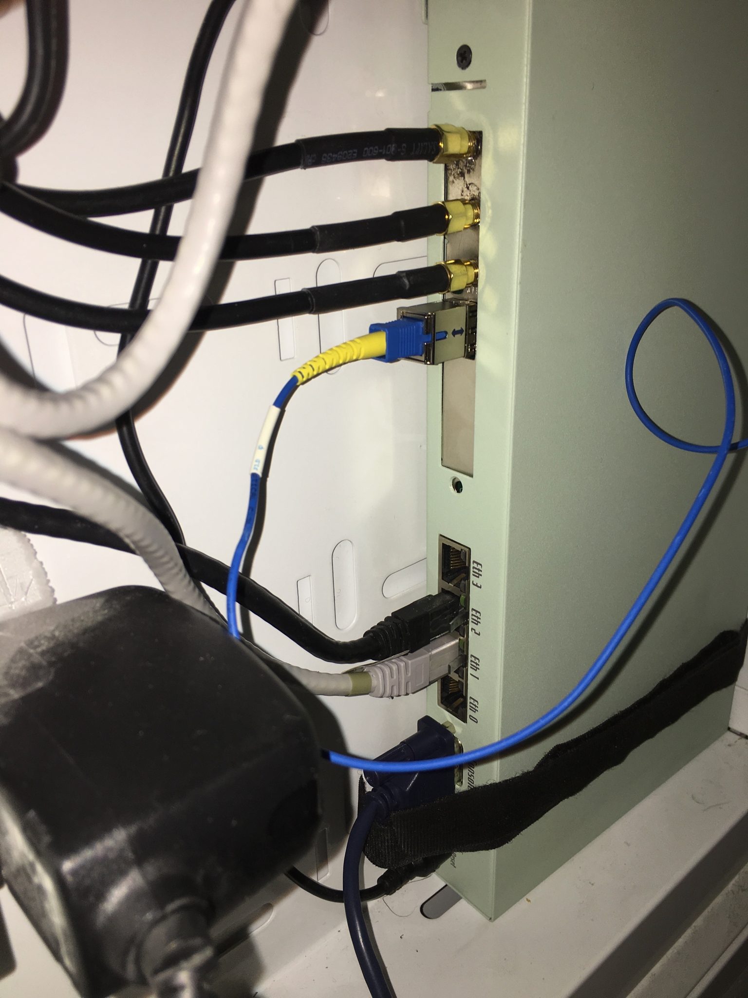
Serial console
My router is located in a small patch cupboard and there was little room for another machine there, so I had to put my OOBM-server somewhere else in my apartment. Luckily I have RJ45 jacks everywhere that are patched to that cupboard so I could very easily run the serial console over the existing CAT6 cables. On the router side I just use a reglar serial cable with DB9 female on one side and a RJ45 male on the other side. On the OOBM-server side I have a simple USB-serial converter followed by a DB9 female to RJ45 female converter. The USB-serial converter shows up in FreeBSD as a regular serial interface like /dev/cuaU0.
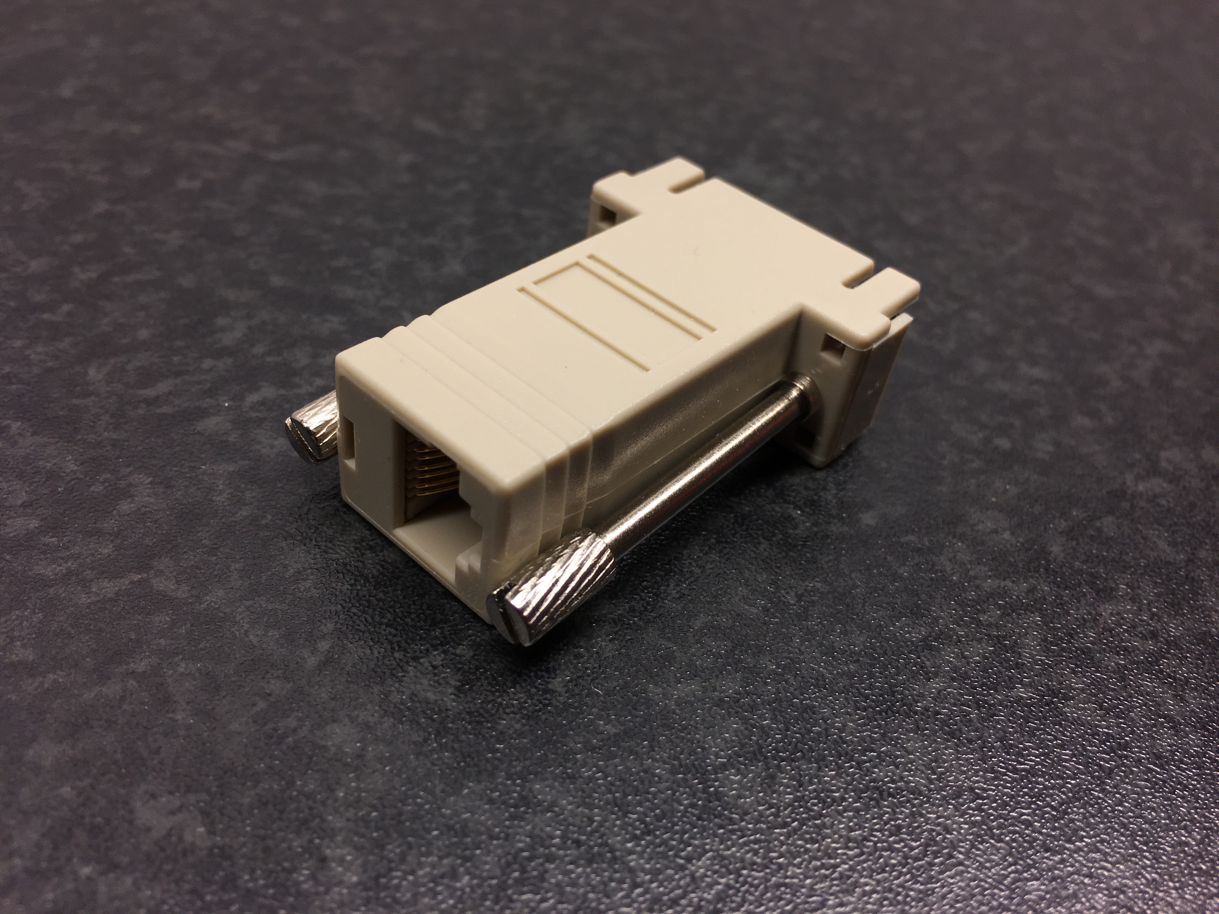
RJ45 to DB9
Out Of Band functionality
Lets put everything together. The first thing i needed to figure out was how to enable the 3g connection remote, but this was pretty simple because the modem can receive sms messages. So I just send some magic/secret sms to the modem that tells it to connect.
Next problem I encountered was that Telia blocks all (?) incoming ports on the mobile connection and since I want to do ssh based administration this was a problem. To work around this problem I went for a solution where the OOBM-server first sets up the PPP connection and then sets up a ssh connection with remote port forwarding to one of my amazon instances. Then I just ssh to the amazon instance on some port and end up on “localhost” on the OOBM-server. On the amazon instance I have created a specific account only used for this purpose that accepts the ssh key used by the OOBM-server.
To put everything together I wrote a small python script that runs every few minutes and checks for valid sms messages on the modem and if it finds such message fires up the PPP connection and then the ssh connection. I will spare you the hazzle of reading my ugly code but here is some pseudo code describing what it does:
m = connect(modem)
if m.send_at("AT") != "OK":
   print "modem is not responsive"
   exit(1)

#Look for valid activation sms
for msg in m.messages():
    if msg.number == "NYNUMBER" && msg.text == "SECRET"
        activate = True
        break

#Try a maximum of three times to set up the connection.
if activate:
    for tries in range(3):
        start_ppp()

        #Check that we can reach internet
        test_connectivity()

        #check that we actually  reach internet via 3G
        verify_route()

        # set up the reverse ssh (ssh -R 31337:localhost:22 remote_server)
        start_ssh()

        #Notify me via pushover that connection is up
        send_push("OOBM link up")

        sleep(1800)

        m.delete_message(all)
        stop_ssh()
        stop_ppp()

        #Notify me via sms that OOBM link is down
        m.send_sms(NUMBER,"OOBM link is down")
        exit(0)
I have omitted the error handling in the pseudo code but I ensure you that the actual script have some.. 😉
The reason i use push messages when the link is up and sms when the link is down is because this modem doesnt have multiplexing and it cant send sms messages while connected.
When the connection is up and running its a simple task to just ssh to remote_server at port 31337 and then login to the OOBM server. From there you can do further ssh connection from the inside of your network or just use the serial console to talk to the router.
% ssh root@remote_server -p31337
root@oobm:~ #
root@oobm:~ # cu -s 57600 -l /dev/cuaU0
Connected

FreeBSD/i386 (gw) (ttyu0)

login:
This is how the setup looks like:
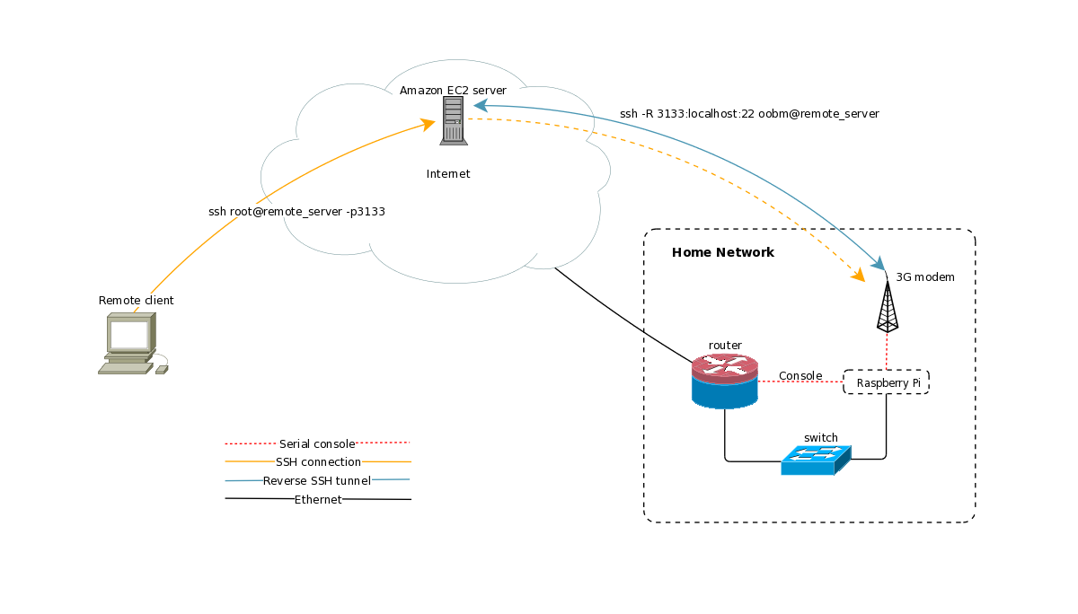
Network diagram
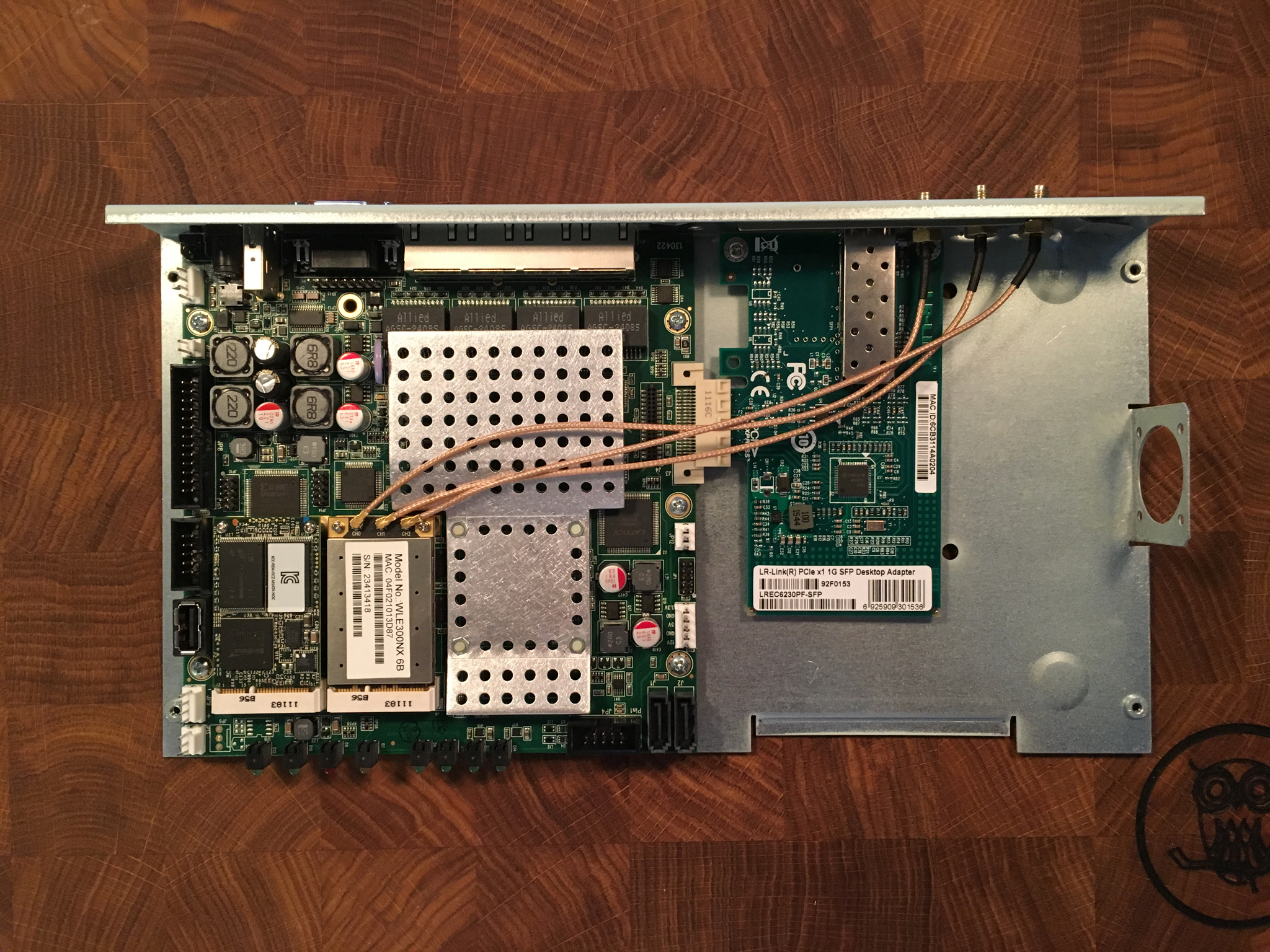
Here is the server installed at its current location
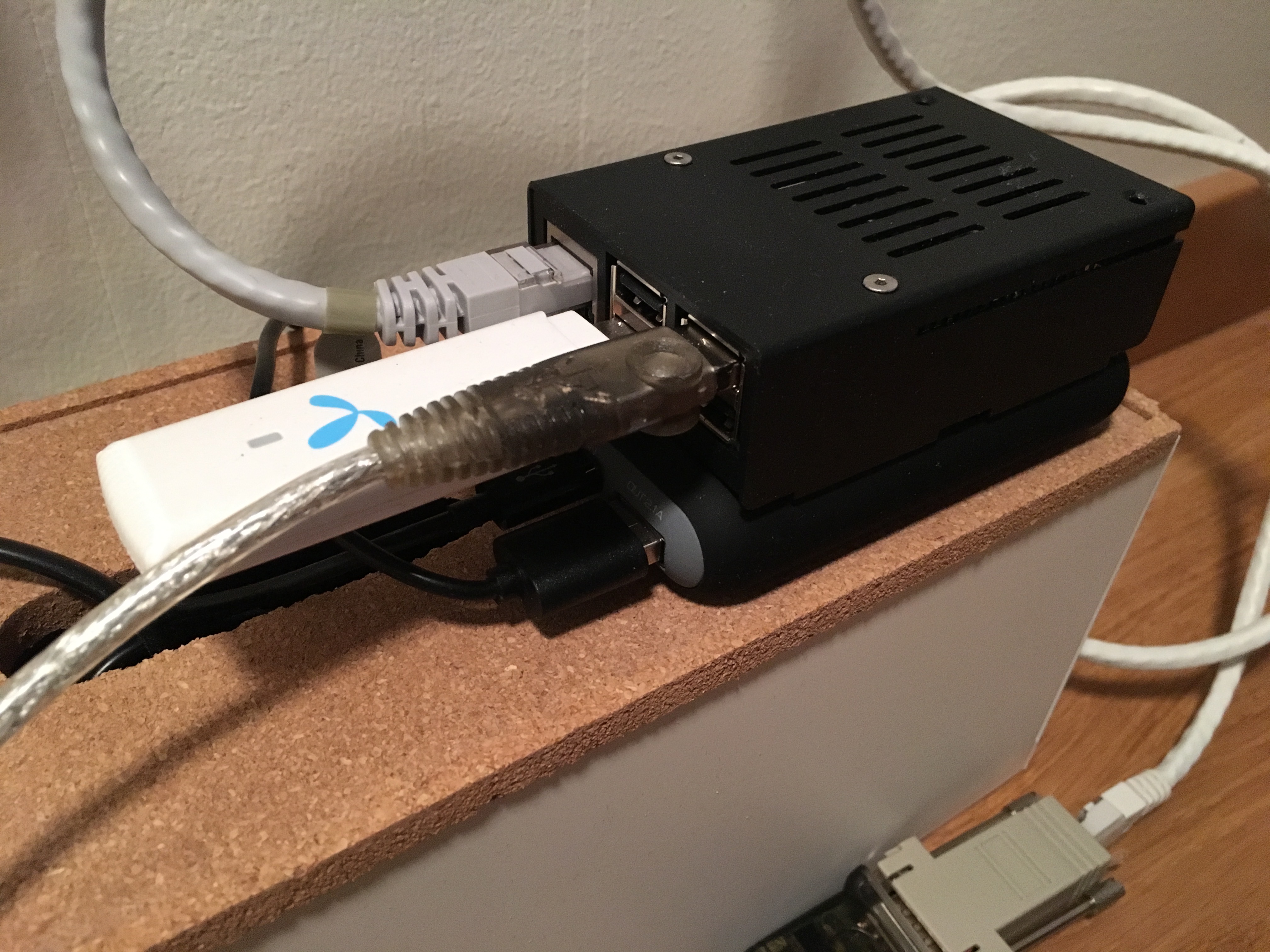
OOBM server on top of power bank