This article describes how to build your own out of band system for your home server.
Background
If you have ever worked professionally with servers you have almost certainly come across some type of out of band management. HP iLO, Dell iDRAC, Huawei iBMC and so on. All more or less based on the IPMI standard. These are basically a small computer that lives independently from your server and give you control over the server even if its turned off for example. You can also virtually mount ISO images and get a console over a web interface and so on. In this way you can even do changes to BIOS settings and so on from a remote location. But probably the most used feature where I work is to simply send power commands to the server like “ipmitool -H <IPMI IP> chassis power off”
The problem for home users is that most consumer grade hardware will not have these features since the IPMI is an actual computer that sits on your motherboards (either directly or in some sort of expansion slot). I will now describe what I did to get a similar (but heavily reduced feature set) for my home server.
Hardware
Computer
First of all you need some hardware, this could be any small computer that will fit inside of closely to your existing server. Its also very good if it could get power from the USB port of the actual server, this way you will not have to have any separate power source for your of of band, also this will have ground in the two systems at the same level which will be good later on.
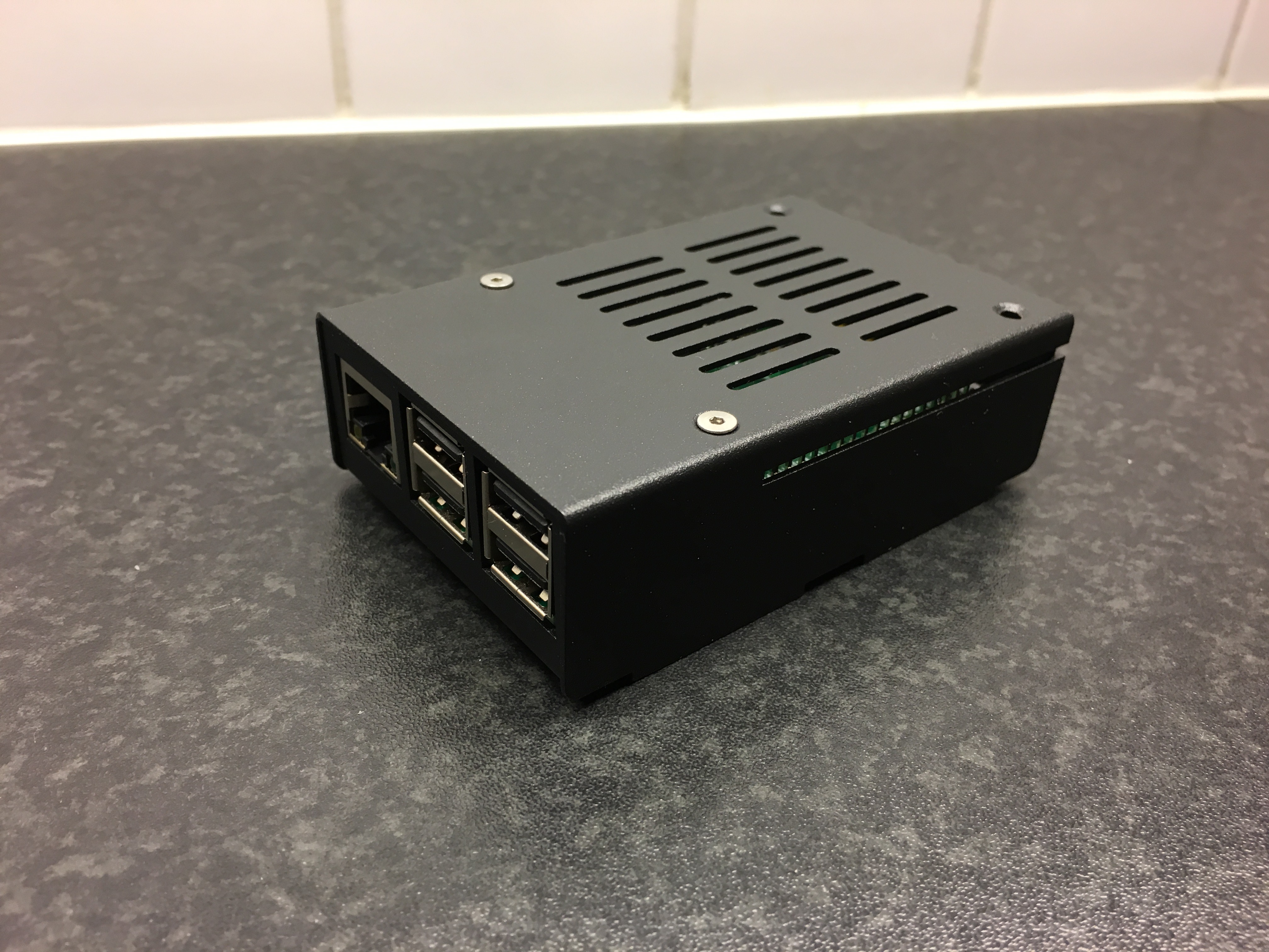
I use a OrangePi Zero and a case which I got off of ebay for about 10USD.
Console
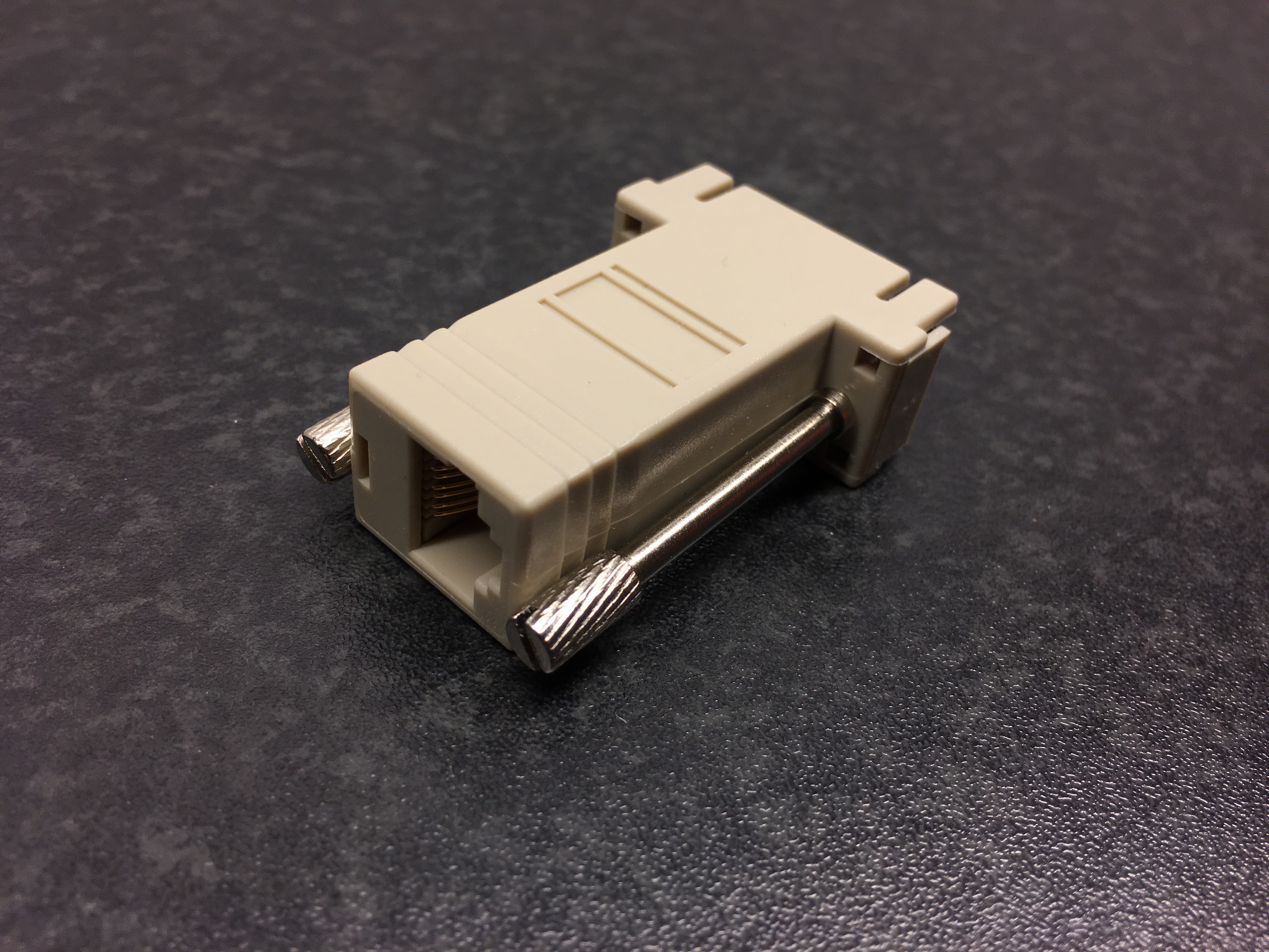
Motherboards these days don’t have a external serial port anymore, but some of them have a internal one which mine luckily had. But to hook up the serial interface of the computer which is a RS-232 interface to the TTL serial interface of the OrangePi I needed to do some conversion or you will damage your Pi, I use a MAX3232 in a package from sparkfun to do this. Just hook upp RX/TX and GND (and 3-5.5V to power it) of both systems to the MAX3232 and you should be good to go. Notice: that if you use the primary serial interface of your Pi you can run into problems if both systems are booting at the same time, because they will interpret each others boot messages as input and will most likely hang the boot.
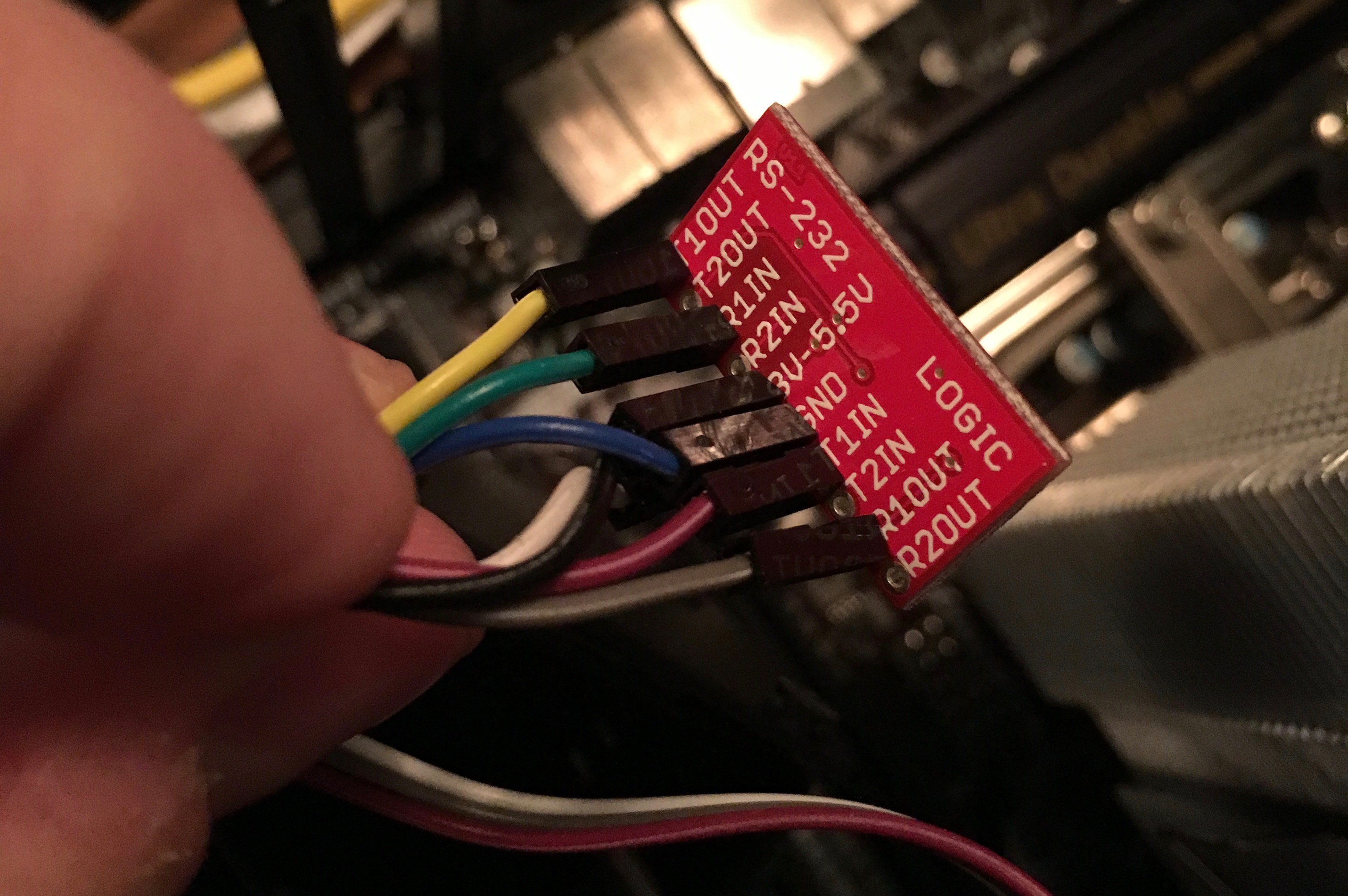
MX3232
Power control
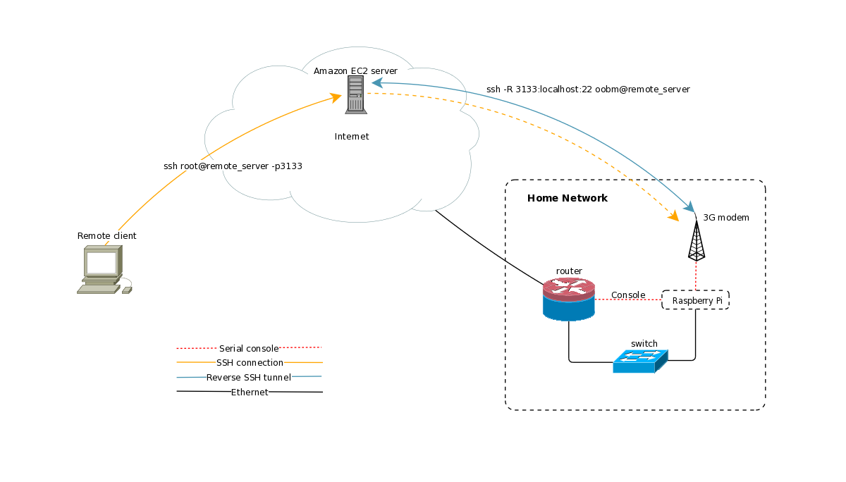
This is one of the most important and also interesting parts of the project. To have console access to a server is pretty common and I have also described this in another “out of band” article where I use console access for my router.
But for this project I wanted to use the GPIO pins of my OrangePi to control the ATX power switch of my server. After some trial and error I got it to work. I use a transistor as a power switch and then I signal the transistor when I want to power on or off the system. A problem I had early on was that when the server (and then also the Pi) got power it immediately turned on the server as well. This was a problem for me because of the console “bug” I described above. To work around this I added a couple of transistors to the system, first a 37kΩ resistor in front of the base of the transistor and also a 10kΩ pull-down resistor the get rid of any signal from the GPIO pin when it is not yet configured. The schematics of the thing looks something like this:
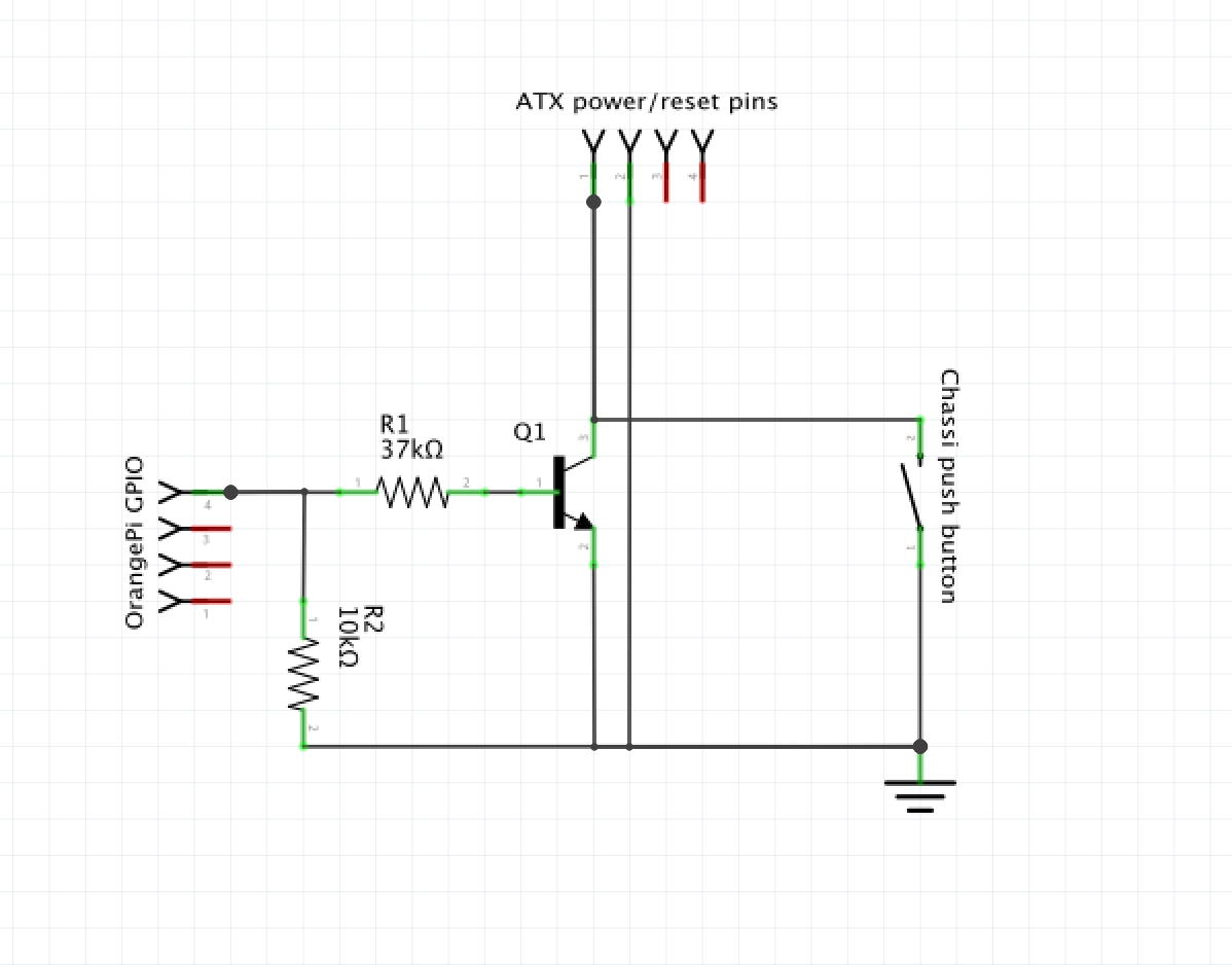
Schematics
This was built using:
Adafruit Perma-Proto Quarter-sized Breadboard
TIP120 transistor
a few pin headers and some resistors
and the end result looks something like this:
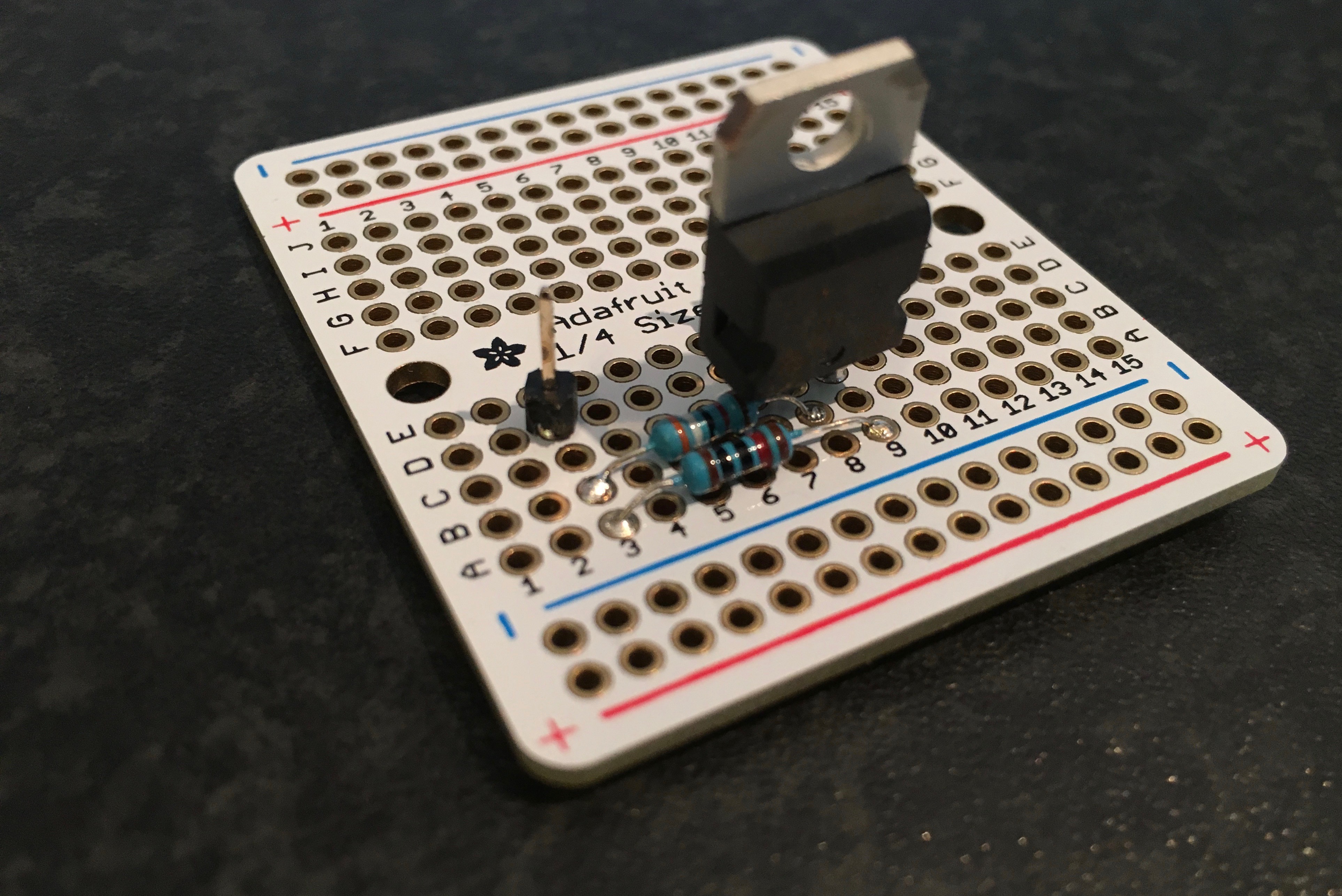
“Front”
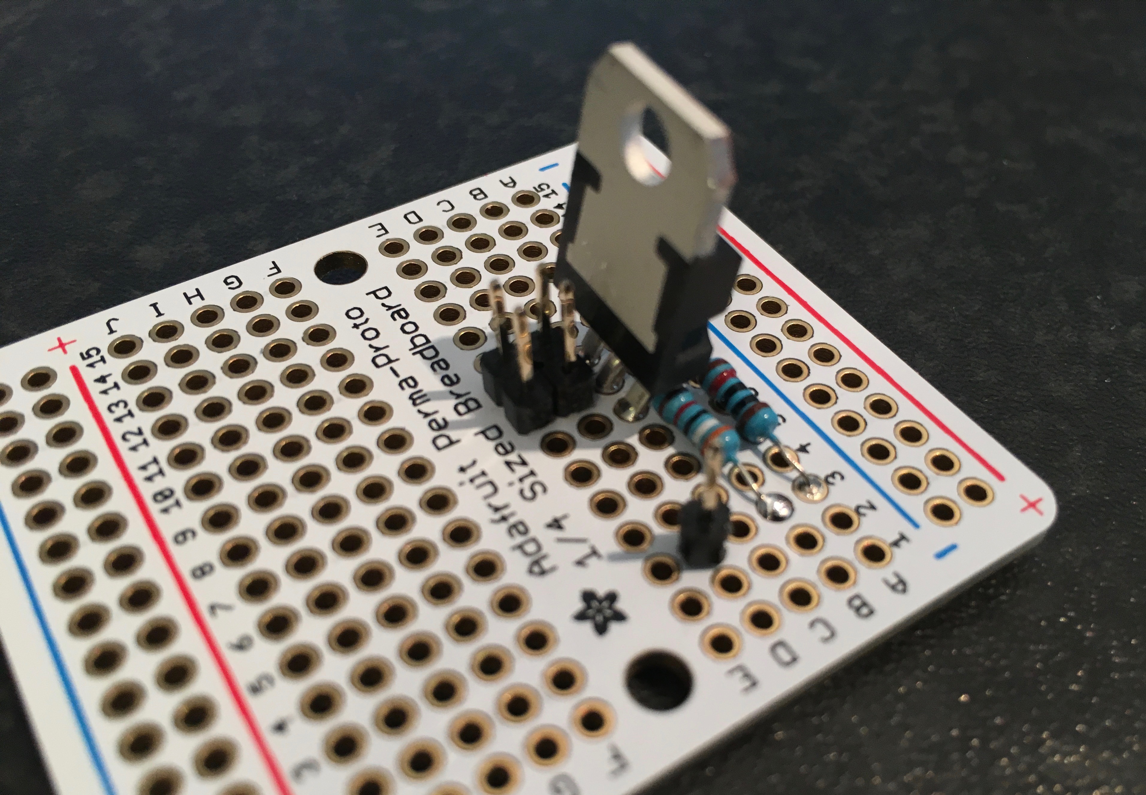
“Back”
The lonely pin is where I connect the GPIO on my OrangePi and to the four other pins I connect the power push button on my case and the pwr+,pwr- pins on the motherboard.
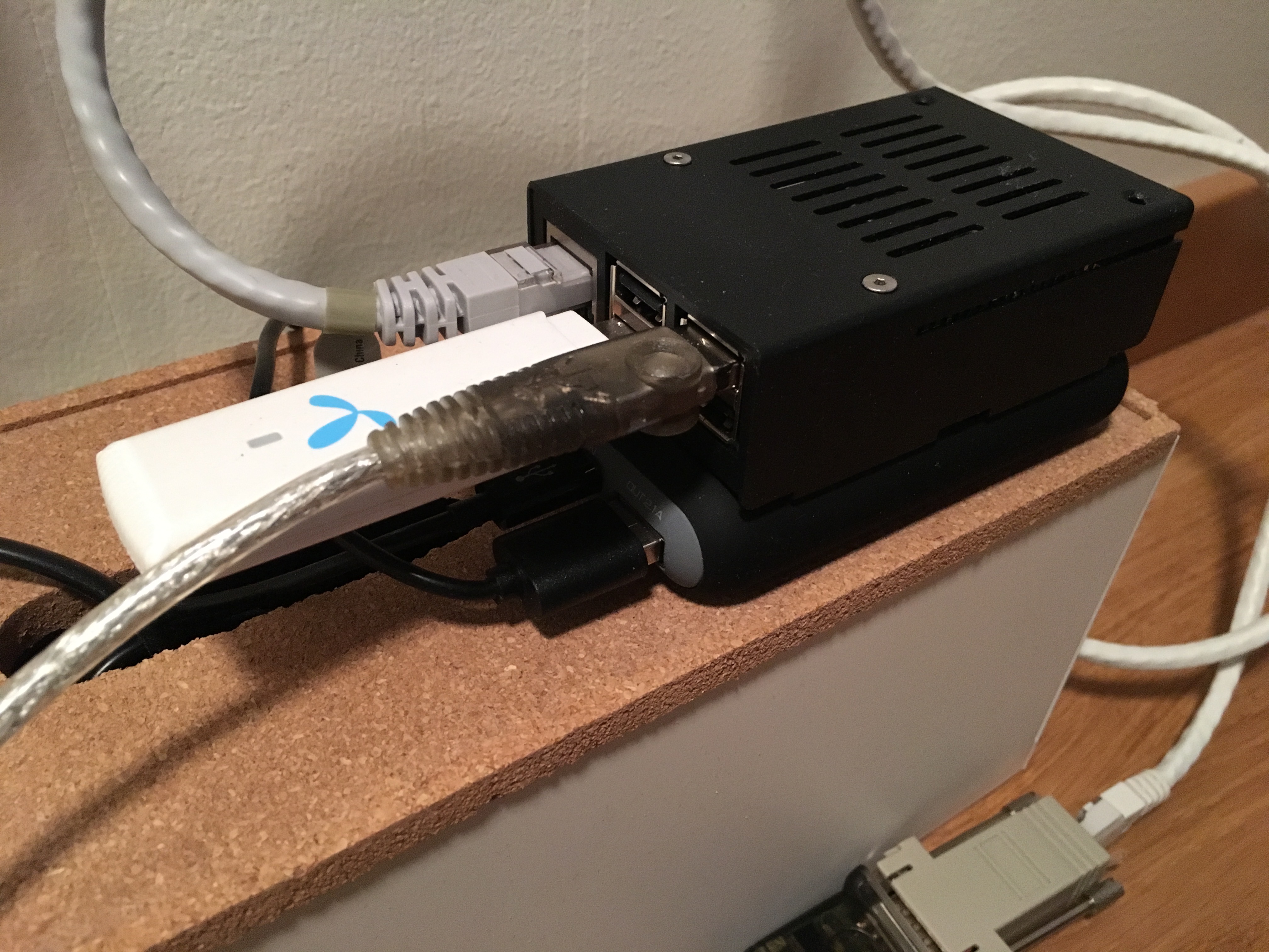
The computer mounted inside my case looks loke this:
OrangePI IPMI
Software
To get the console output working from there server we need to change a few files. You will need something like this in /etc/ttys
ttyu0 "/usr/libexec/getty 3wire" vt100 on secure
and something like this to /boot/loader.conf
console="comconsole"
I have not yet written any scripts and so on but it’s really easy to use use standard CLI commands in FreeBSD to control the GPIO.
# Setup of the pin
root@orangepi:~ # gpioctl -n 12 pwr
root@orangepi:~ # gpioctl -c pwr out
# Power on (if off)
root@orangepi:~ # gpioctl pwr 1 ; gpioctl pwr 0
# Soft shutdown (if on)
root@orangepi:~ # gpioctl pwr 1 ; gpioctl pwr 0
# Forceful shutdown
root@orangepi:~ # gpioctl pwr 1 ; sleep 5; gpioctl pwr 0
Summing up
This project took me about 3-4 evenings to finish including a lot of trial and error in the beginning and now I have a system where I can actually from a remote location reboot my server. I also get console access early enough to change the options to the kernel or even change kernel before booting. Since I spent only about 25USD in total on this project I’m really satisfied with the result. We will have to see how good it actually works in a real situation, like a kernel panic or whatever.