Background
We where frustrated at work about the central IT organisation blocking outgoing 123/udp connections. This gave us the idea to buy a GPS controlled NTP server like this one: https://www.meinbergglobal.com/english/products/rack-mount-1u-ntp-server.htm. While doing some research on this subject I found that alot of people seem to build their own stratum 1 NTP servers at home. So I decided to build one myself to use at home.
Prerequisites
There is alot of information floating around on this subject but I wanted to use FreeBSD and Raspberry Pi. It took me a while to figure this out but I bought this set of hardware:
Raspberry Pi 2 Model B
Adafruit Raspberry Pi Case
Adafruit Ultimate GPS Breakout
Adafruit Perma-Proto HAT
External antenna
Basic setup
There is now a new kernel module named gpiopps written by ian@freebsd.org that you can use to get PPS input on any gpio pin. To configure what gpio pin to use you need to rebulid the device tree of your raspberry pi (/usr/src/sys/boot/fdt/dts/arm/rpi2.dts). This is the changes i made:
# svnlite diff
Index: rpi2.dts
===================================================================
--- rpi2.dts	(revision 309114)
+++ rpi2.dts	(working copy)
@@ -337,6 +337,13 @@
 		broadcom,depth = ;		/* Set by VideoCore */
 	};

+
+ 	pps@0  {
+		compatible = "pps-gpio";
+		gpios = <&gpio 17 0>;
+		status = "okay";
+	};
+
 	leds {
 		compatible = "gpio-leds";
and then rebuilt the tree
# cd /usr/src/sys/tools/fdt
# setenv MACHINE arm
# ./make_dtb.sh /usr/src/sys /usr/src/sys/boot/fdt/dts/arm/rpi2.dts rpi2.dtb
# cp rpi2.dtb /boot/msdos
Then you can hook up the pps output of the GPS to gpio pin 17 of your raspberry pi and make sure gpiopps is loaded by adding this line to /boot/loader.conf.
gpiopps_load="YES"
Reboot the pi and then you should see something like this in the boot messages
gpiopps0:  on ofwbus0
gpiopps0: PPS input on gpio0 pin 17
Physical setup
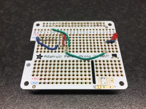
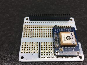
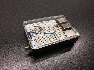
For the physical setup I used the Pi, a case and the “perma proto hat” and did some simple soldering to hook up the serial interface of the GPS to the uart serial interface of the Pi, and of course the PPS output to gpio pin 17. I also added a LED to the pps output so I can visually see when I have a working PPS signal.
Finished product:
GPS configuration
The GPS is actually very easy to talk to. It has a serial interface configured to 9600 baud by default and a dedicated PPS output.
To control the GPS you can send basic text-strings to the unit, for example setting the update rate to 1Hz:
# printf '$PMTK251,57600*2C\r\n' > /dev/cuau0 (Set baudrate to 57600)
# printf '$PMTK314,0,1,0,0,0,0,0,0,0,0,0,0,0,0,0,0,0,0,0*29\r\n' > /dev/cuau0 (ask only for GPRMC sentences)
# printf '$PMTK220,1000*1F\r\n' > /dev/cuau0 (echo sentences once a second)
# printf '$PMTK300,1000,0,0,0,0*1C\r\n' > /dev/cuau0 (update fix once a second)
If you want a complete set of instructions(commands) you can send to device please see the command set sheet.
NTP configuration
I have four different kind of time sources configured on my stratum 1 server.
1. External time sources (internet). In Sweden we have a pretty neat project at ntp.se where they have built custom ntp-servers using FPGAs and atomic clocks.They should be able to server time at 10Gbit/s line rate. You can read more about this here: http://www.ntp.se. I use all of these servers as reference clocks.
2. Local servers that run ntpd. Just my gateway and my server. In the case that all other references fail they can still discipline each other.
3. PPS input from the GPS module. This is the main thing about this article. The GPS outputs a pulse every second that is then used to discipline ntpd.
4. GMEA data from the GPS module. The GPS also outputs coordinates and times on the serial console. But these timestamps are pretty imprecise, at best its close within a second. (But since we also have PPS this is good enough)
You can see my ntp.conf here below but I will only talk about the GPS-stuff from now on.
I use two different drivers in ntpd. 20 and 22. These are the NMEA and PPS drivers. My settings for the PPS driver is pretty basic, it will automatically look for /dev/pps0 and try to fix to a pps signal. The gpiopps driver creates gpiopps0 so I have added “link gpiopps0 pps0” to /etc/devfs.conf
For the NMEA driver we have a few more settings. First of all “mode 17” sets what type of output the look for from the GPS and what baudrate to use. From the driver documentation you find that bit 0 is used to set processing of $GPMRC sentences from the GPS. Bit 4-6 is used to set baudrate and decimal “16” is 9600. So 9600+$GPMRC=17 right? 🙂 This driver looks for /dev/gps0 by default so I have added “link cuau0 gps0” to /etc/devfs.conf
The fudge time2 is used to compensate for the delays we have in the serial interface of the GPS to make it match PPS more closely.
Please refer to the driver documentation for more settings:
http://doc.ntp.org/4.2.8p8/drivers/driver20.html
http://doc.ntp.org/4.2.8p8/drivers/driver22.html
# Allow traffic to external servers
restrict 194.58.203.20 mask 255.255.255.255 nomodify notrap noquery
restrict 194.58.203.148 mask 255.255.255.255 nomodify notrap noquery
restrict 194.58.204.20 mask 255.255.255.255 nomodify notrap noquery
restrict 194.58.204.148 mask 255.255.255.255 nomodify notrap noquery
restrict 194.58.202.20 mask 255.255.255.255 nomodify notrap noquery
restrict 194.58.202.148 mask 255.255.255.255 nomodify notrap noquery
restrict 194.58.205.20 mask 255.255.255.255 nomodify notrap noquery
restrict 194.58.205.148 mask 255.255.255.255 nomodify notrap noquery

# Allow traffic to internal servers
restrict 172.25.0.25 mask 255.255.255.255 nomodify notrap noquery
restrict 172.25.0.1 mask 255.255.255.255 nomodify notrap noquery


# PPS
server 127.127.22.0 flag3 0

# NMEA
server 127.127.20.0 mode 17
fudge 127.127.20.0 time2 +0.767

# Servers
server 194.58.203.20 iburst  prefer
server 194.58.203.148 iburst
server 194.58.204.20 iburst
server 194.58.204.148 iburst
server 194.58.202.20 iburst
server 194.58.202.148 iburst
server 194.58.205.20 iburst
server 194.58.205.148 iburst
server 172.25.0.25
server 172.25.0.1

driftfile /var/db/ntp.drift

# save ntp performance stats
statistics loopstats
statsdir /var/log/ntp/
filegen peerstats file peerstats type day enable
filegen loopstats file loopstats type day enable
filegen clockstats file clockstats type day enable
Running ntpd
So now when we have configured ntpd how does it actually work? This is some output from ntpq -p efter some 30mins of ntpd running:
root@ntp:/dev # ntpq -p
     remote           refid      st t when poll reach   delay   offset  jitter
==============================================================================
 torus.pean.org  172.25.0.10      2 u   20   64  377    0.417    0.816   0.033
 gw.pean.org     172.25.0.10      2 u   18   64  377    0.609    0.462   0.102
oPPS(0)          .PPS.            0 l    5   64  377    0.000    0.133   0.011
xGPS_NMEA(0)     .GPS.            0 l    4   64  377    0.000   62.005   6.586
*gbg1.ntp.se     .PPS.            1 u   21   64  377    7.467    0.052   0.054
+gbg2.ntp.se     .PPS.            1 u   25   64  377    7.514    0.167   0.074
+mmo1.ntp.se     .PPS.            1 u   14   64  377   11.469    0.127   0.221
+mmo2.ntp.se     .PPS.            1 u   22   64  377   11.386    0.152   0.139
+sth1.ntp.se     .PPS.            1 u   12   64  377    2.087    0.130   0.235
+sth2.ntp.se     .PPS.            1 u   17   64  377    2.255    0.158   0.292
-svl1.ntp.se     .PPS.            1 u   13   64  377    6.686   -0.118   1.343
+svl2.ntp.se     .PPS.            1 u    6   64  377    6.015    0.144   1.177
The o in oPPS denotes that ntpd have PPS signal. The x in xGPS_NMEA denotes that this source is marked as a false ticker. The reason for this could be that I have entered a to large fudge factor, its seem to be running 62ms fast at this point. I will keep ntpd running for a few hours and the try to adjust the time fudge accordingly.


